Clustered HA SAN/NAS Solutions using ZFS
Contents
Overview
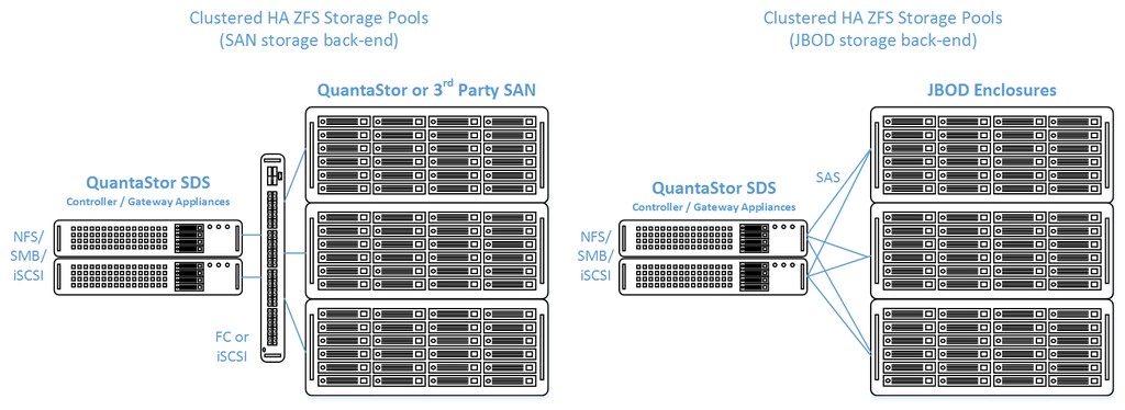
QuantaStor's clustered storage pool configurations ensure high-availability (HA) in the event of a node outage or storage connectivity to the active node is lost. From a hardware perspective a QuantaStor deployment of one or more clustered storage pools requires at least two QuantaStor appliances so that automatic fail-over can occur in the event that the active appliance goes offline. Another requirement of these configurations is that the disk storage devices for the highly-available pool cannot be in either of the server units. Rather the storage must come from an external source which can be as simple as using one or more SAS JBOD enclosures or for higher performance configurations could be a SAN delivering block storage (LUNs) to the QuantaStor front-end appliances over FC (preferred) or iSCSI. The following two sections outline the minimum hardware requirements for each.
Highly-Available SAN/NAS Storage (Tiered SAN, ZFS based Storage Pools)
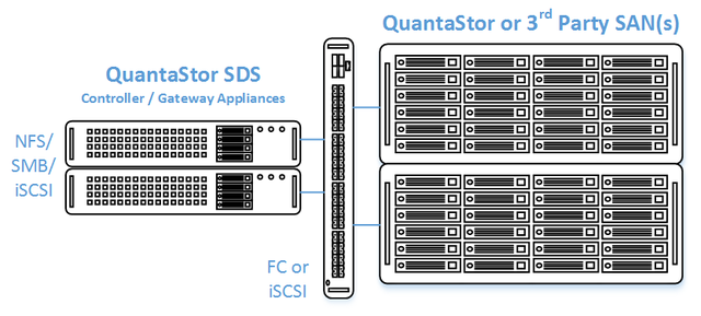
In this configuration the QuantaStor front-end controller appliances are acting as a gateway to the storage in the SANs on the back-end. QuantaStor has been tested with NetApp and HP MSA 3rd party SANs as back-end storage as well as with QuantaStor SDS as a back-end SAN. Please contact support@osnexus.com for the latest HCL for 3rd party SAN support or to get additional SAN support added to the HCL.
Minimum Hardware Requirements
- 2x (or more) QuantaStor appliances which will be configured as front-end controller nodes
- 2x (or more) QuantaStor appliance configured as back-end data nodes with SAS or SATA disk
- High-performance SAN (FC/iSCSI) connectivity between front-end controller nodes and back-end data nodes
Setup Process
All Appliances
- Add your license keys, one unique key for each appliance
- Setup static IP addresses on each appliance (DHCP is the default and should only be used to get the appliance initially setup)
- Right-click on the storage system and set the DNS IP address (eg 8.8.8.8), and your NTP server IP address
Back-end Appliances (Data Nodes)
- Setup each back-end data node appliance as per basic appliance configuration with one or more storage pools each with one storage volume per pool.
- Ideal pool size is 10 to 20 drives, you may need to create multiple pools per back-end appliance.
- SAS is recommended but enterprise SATA drives can also be used
- HBA(s) or Hardware RAID controller(s) can be used for storage connectivity
Front-end Appliances (Controller Nodes)
- Connectivity between the front-end and back-end nodes can be FC or iSCSI
FC Based Configuration
- Create Host entries, one for each front-end appliance and add the WWPN of each of the FC ports on the front-end appliances which will be used for intercommunication between the front-end and back-end nodes.
- Direct point-to-point physical cabling connections can be made in smaller configurations to avoid the cost of an FC switch. Here's a guide that can help with some advice on FC zone setup for larger configurations using a back-end fabric.
- If you're using a FC switch you should use a fabric topology that'll give you fault tolerance.
- Back-end appliances must use Qlogic QLE 8Gb or 16Gb FC cards as QuantaStor can only present Storage Volumes as FC target LUNs via Qlogic cards.
iSCSI Based Configuration
- It's important but not required to separate the networks for the front-end (client communication) vs back-end (communicate between the control and data appliances).
- For iSCSI connectivity to the back-end nodes, create a Software iSCSI Adapter by going to the Hardware Controllers & Enclosures section and adding a iSCSI Adapter. This will take care of logging into and accessing the back-end storage. The back-end storage appliances must assign their Storage Volumes to all the Hosts for the front-end nodes with their associated iSCSI IQNs.
- Right-click to Modify Network Port of each port you want to disable client iSCSI access on. If you have 10GbE be sure to disable iSCSI access on the slower 1GbE ports used for management access and/or remote-replication.
HA Network Setup
- Make sure that eth0 is on the same network on both appliances
- Make sure that eth1 is on the same but separate network from eth0 on both appliances
- Create the Site Cluster with Ring 1 on the first network and Ring 2 on the second network, both front-end nodes should be in the Site Cluster, back-end nodes can be left out. This establishes a redundant (dual ring) heartbeat between the front-end appliances which will be used to detect hardware problems which in turn will trigger a failover of the pool to the passive node.
HA Storage Pool Setup
- Create a Storage Pool on the first front-end appliance (ZFS based) using the physical disks which have arrived from the back-end appliances.
- QuantaStor will automatically analyze the disks from the back-end appliances and stripe across the appliances to ensure proper fault-tolerance across the back-end nodes.
- Create a Storage Pool HA Group for the pool created in the previous step, if the storage is not accessible to both appliances it will block you from creating the group.
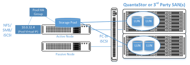
- Create a Storage Pool Virtual Interface for the Storage Pool HA Group. All NFS/iSCSI access to the pool must be through the Virtual Interface IP address to ensure highly-available access to the storage for the clients.
- Enable the Storage Pool HA Group. Automatic Storage Pool fail-over to the passive node will now occur if the active node is disabled or heartbeat between the nodes is lost.
- Test pool failover, right-click on the Storage Pool HA Group and choose 'Manual Failover' to fail-over the pool to another node.
Standard Storage Provisioning
- Create one or more Network Shares (CIFS/NFS) and Storage Volumes (iSCSI/FC)
- Create one or more Host entries with the iSCSI initiator IQN or FC WWPN of your client hosts/servers that will be accessing block storage.
- Assign Storage Volumes to client Host entries created in the previous step to enable iSCSI/FC access to Storage Volumes.
Diagram of Completed Configuration
Minimum Hardware Requirements
- 2x QuantaStor storage appliances acting as storage pool controllers
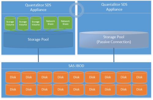
- 1x (or more) SAS JBOD connected to both storage appliances
- 2x to 100x SAS HDDs and/or SAS SSDs for pool storage, all data drives must be placed in the external shared JBOD. Drives must be SAS that support Multi-port and SCSI3 Reservations, SATA drives are not supported.
- 1x hardware RAID controller (for mirrored boot drives used for QuantaStor OS operating system)
- 2x 500GB HDDs (mirrored boot drives for QuantaStor SDS operating system)
- Boot drives should be 100GB to 1TB in size, both enterprise HDDs and DC grade SSD are suitable
Setup Process
Basics
- Login to the QuantaStor web management interface on each appliance
- Add your license keys, one unique key for each appliance
- Setup static IP addresses on each node (DHCP is the default and should only be used to get the appliance initially setup)
- Right-click to Modify Network Port of each port you want to disable iSCSI access on. If you have 10GbE be sure to disable iSCSI access on the slower 1GbE ports used for management access and/or remote-replication.
HA Network Config
- Right-click on the storage system and set the DNS IP address (eg 8.8.8.8), and your NTP server IP address
- Make sure that eth0 is on the same network on both appliances
- Make sure that eth1 is on the same but separate network from eth0 on both appliances
- Create the Site Cluster with Ring 1 on the first network and Ring 2 on the second network. This establishes a redundant (dual ring) heartbeat between the appliances.
HA Storage Pool Creation Setup
- Create a Storage Pool (ZFS based) on the first appliance using only disk drives that are in the external shared JBOD
- Create a Storage Pool HA Group for the pool created in the previous step, if the storage is not accessible to both appliances it will block you from creating the group.
- Create a Storage Pool Virtual Interface for the Storage Pool HA Group. All NFS/iSCSI access to the pool must be through the Virtual Interface IP address to ensure highly-available access to the storage for the clients. This ensures that connectivity is maintained in the event of fail-over to the other node.
- Enable the Storage Pool HA Group. Automatic Storage Pool fail-over to the passive node will now occur if the active node is disabled or heartbeat between the nodes is lost.
- Test pool fail-over, right-click on the Storage Pool HA Group and choose 'Manual Fail-over' to fail-over the pool to another node.
Storage Provisioning
- Create one or more Network Shares (CIFS/NFS) and Storage Volumes (iSCSI/FC)
- Create one or more Host entries with the iSCSI initiator IQN or FC WWPN of your client hosts/servers that will be accessing block storage.
- Assign Storage Volumes to client Host entries created in the previous step to enable iSCSI/FC access to Storage Volumes.


