Scale-out File Setup (ceph)
QuantaStor supports Scale-out NAS with access via the native CephFS, SMB, and NFS protocols. QuantaStor integrates with and extends Ceph storage technology to deliver scale-out NAS storage with integration with Active Directory, hardware integration and monitoring, active cluster management and monitoring and much more.
Introduction to QuantaStor Scale-out NAS using CephFS technology
QuantaStor with Ceph is a highly-available and elastic SDS platform that enables scaling object storage environments from a small 3x system configuration to hyper-scale storage grid configurations with 100s of systems. Within a QuantaStor storage grid, up to 20x Ceph Clusters may be managed and automated. QuantaStor's Storage Grid management technology provides single pane of management for all the systems and API, Web UI, and CLI access is available on all systems at the same time. QuantaStor's powerful configuration, monitoring and management features elevate Ceph to an enterprise platform making it easy to setup and maintain large configurations with ease. The following guide covers how to setup scale-out NAS storage, monitor, and maintain it.
This section will introduce various Ceph component terms and concepts to enable confident creation and administration of a Scale-out Object solution using QuantaStor.
Ceph Terminology & Concepts
This section will introduce Ceph terms and concepts to familiarize oneself with to become more proficient with Ceph Cluster administration in QuantaStor. This discussion will address general concepts surrounding Ceph. To implement Ceph in QuantaStor it is recommended to see Getting Started to quickly implement Ceph. Getting Started can be found at Storage Management --> Storage System --> Storage System --> Getting Started (toolbar).
Getting Started in Administration guide.
Further Information: Introduction to Ceph.
Ceph Cluster
A Ceph Cluster is a group of three or more systems that have been clustered together using the Ceph storage technology. Ceph requires a minimum of three nodes to create a cluster so that quorum may be established across the Ceph Monitors. Wikipedia Quorum (distributed computing).
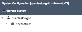
In QuantaStor based Ceph configurations, QuantaStor systems must first be combined into a Storage Grid. After the Storage Grid is formed one more more Ceph Clusters may be created within the Storage Grid. In the example above the Storage Grid is comprised of a single Ceph Cluster. When the Ceph Cluster is initially created QuantaStor automatically deploys 3x Ceph Monitors within the new Ceph Cluster.
Ceph Monitor
The Ceph Monitors form a Paxos The Part-Time Parliament cluster for the management of cluster membership, configuration information, and state. Paxos is an algorithm (developed by Leslie Lamport in the late 80s) which uses a three-phase consensus protocol to ensure that cluster updates can be done in a fault-tolerant timely fashion even in the event of a node outage or node that is acting improperly. Ceph uses the algorithm so that the membership, configuration and state information is updated safely across the cluster in an efficient manner. Since the algorithm requires a quorum of nodes to agree on any given change an odd number of systems (three or more) are required for any given Ceph cluster deployment.
During initial Ceph cluster creation, QuantaStor will configure the first three systems to have active Ceph Monitor services. Configurations with more than 16 nodes should add two additional monitors. This can be done through the QuantaStor web user interface in the Scale-out Storage Configuration section.
In a Ceph cluster with 3x monitors a minimum of 2x monitors must be online at all times. If only one monitor (or none) are running then storage access will is automatically disabled until quorum among monitors may be reestablished. In larger clusters with 5x monitors then 3x monitors must be online at all times to maintain quorum and storage accessibility.
Ceph Object Storage Daemon / OSD
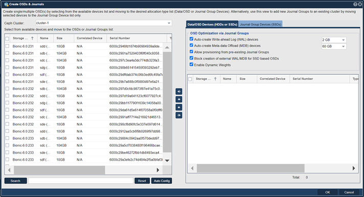
Navigation: Scale-out Storage Configuration --> Data & Journal Devices --> Data & Journal Devices --> Create OSDs & Journals (toolbar)
The Ceph Object Storage Daemon, known as the OSD, is a daemon process that reads and writes data and generally maps 1-to-1 to a HDD or a SSD device. OSD devices may be used by multiple Storage Pools so after the OSDs are added one may allocate pools for file, block, and object storage which all use the available OSDs in the cluster to store their data.
QuantaStor Scale-out SAN with Ceph deployments must have at least 3x OSDs per system, making 9x OSDs total the minimum number OSDs. QuantaStor 5 and newer versions use the BlueStore OSD storage back-end. For additional BlueStore information see, New in Luminous: BlueStore.
N.B., for ease of use there is an Auto Config button that will optimize selection of available devices.
Journal Groups
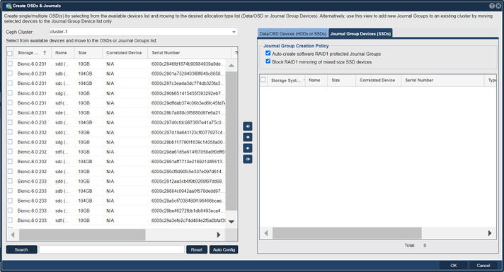
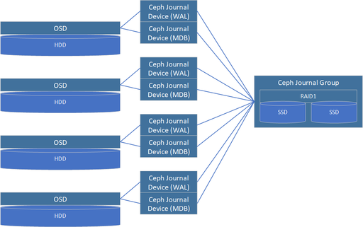
Journal Groups are used to boost the performance of OSDs. Each Journal Group can provide a performance boost for 5x to 30x OSD devices depending on the speed of the storage media used to create a given Journal Group. Journal Groups are typically created using a pair of SSDs which QuantaStor combines into software RAID1 mirror. Once created Journal Groups provide high performance, low latency, storage from which Ceph Journal Devices may be provisioned and attached to new OSDs to boost performance. Because Journal Groups must sustain high write loads over a period of years only datacenter (DC) grade / enterprise grade flash media should be used to create them. Journal Groups can be created using all types of flash storage media including NVMe, PMEM, SATA SSD, or SAS SSD.
Journal Devices are provisioned from Journal Groups. Journal Devices come in two types, Write-Ahead-Log (WAL) devices and Meta-data DB (MDB) devices. QuantaStor automatically provisions WAL devices to be 2GB in size and MDB devices can be 3GB, 30GB (default), or 300GB in size.
Journal Groups are not required but are highly recommended when creating HDD based OSDs. With SSD based OSDs it is not recommended to assign them external WAL and MDB devices from Journal Groups. Rather the MDB and WAL storage for SSDs will be allocated out of a small portion of the underlying OSD data device. With platter/HDD based OSDs we highly recommend the creation of Journal Groups so that each OSD can have both an external WAL device and a external MDB device.
NVMe and 3D XPoint flash storage media are the best storage types for creating Journal Groups due to their high throughput and IOPS performance. We recommend allocating 100MB/sec and 32GB of capacity for each HDD based OSD. For example, a system with 60x HDD based OSDs would require 60x100MB/sec or 6000MB/sec of Journal Group throughput. If NVMe devices are selected that can do 2000MB/sec then three Journal Groups will be required and a total of 6x NVMe SSDs (3x RAID1 Journal Groups). Capacity wise 60x HDDs will require 60x32GB of storage for all the WAL and MDB devices to be created or what amounts to 1.92TB of provisionable Journal Group capacity. One possible design to meet both the performance and the capacity requirements would be to make the 3x Journal Groups using a total of 6x 800GB NVMe devices with a 3x DWPD endurance.
Write-Ahead Log (WAL) Journal Devices
WAL Journal Devices are provisioned from Journal Groups and are then attached to new OSDs when they are created. WAL devices accelerate write performance. When a write request is received by an OSD it is able to write the data to low-latency stable flash media very quickly to complete the write. Data can then be written lazily to the HDD as time allows without risk of losing data due to a sudden system power outage.
Meta-data Database (MDB) Journal Devices
MDB Journal Devices effectively boost both read and write performance as they contain all the Bluestore filesystem metadata. Rather than having to write small blocks of metadata to HDDs which have low IOPS performance and external MDB device on flash media can sustain high IOPS loads and in turn greatly boosts performance.
Hardware RAID
Although Hardware RAID may be used in Ceph Clusters as an underlying storage abstraction for OSDs it is generally not recommended. It does have applications in very large Ceph clusters (ie. 1000s of OSDs) and with clusters comprised of servers with limited RAM and CPU core count. Roughly speaking each OSD requires approximately 2GB of RAM and a 1GHz fractional CPU core. A server with 60x HDD based OSDs will require a large dual-processor configuration and 192GB of RAM. By combining disks using HW RAID these requirements are reduced 5:1. QuantaStor does have integrated hardware RAID management and monitoring to manage configurations that use hardware RAID. But again, we do not recommend the use of HW RAID except in specialized configurations and in hyper-scale configurations.
Ceph Placement Groups (PGs)
Ceph Pools do not write data directly to OSDs, rather there is an abstraction layer between each Ceph Pool and the OSDs comprised of Placement Groups, PGs. Each PG can be thought of as a logical stripe across a group of OSDs. Ceph Pools created with a replica=2 storage layout will have PGs that each reference 2x OSDs. Similarly a Ceph Pool with an erasure-coding layout of K8+2M would have PGs that each span 10x OSDs. When creating new File, Block, or Object Storage Pools with QuantaStor you have control over the number of PGs to be created using the Scaling Factor option. If a given Ceph Cluster is to be used for a single type of storage such as File or Object then one would set the Scaling Factor to 100%. If it is expected that a given Ceph Cluster will be used for 30% Object storage and 70% File storage then those Storage Pools should be allocated with those Scaling Factors respectively. Your choice for the Scaling Factor for any given pool should be a best guess. The PG count can be adjusted later to provide better optimization of storage distribution and balancing across the OSDs in the future if required.
Ceph CRUSH Maps and Resource Domains
Ceph supports the ability to organize placement groups, which provide data mirroring across OSDs, so that high-availability and fault-tolerance can be maintained even in the event of a rack or site outage. By defining failure-domains, such as a Rack of systems, a Site, or Building, a map can be created so that Placement Groups are intelligently laid out to ensure high-availability despite the outage of one or more failure-domains, depending on the level of redundancy.
This intelligent map is called the Ceph CRUSH map (Controlled Replication Under Scalable Hashing), standing for Controlled, Scalable, Decentralized Placement of Replicated Data, and it defines how to mirror data in the Ceph cluster to ensure optimal performance and availability.
Creating CRUSH maps manually can be a complex process, so QuantaStor creates and configures CRUSH maps automatically, saving a large degree of administrative overhead. To facilitate automatic CRUSH map management, detail regarding where each QuantaStor system is deployed must be provided. This is done by creating a tree of Resource Domains via the WebUI (or via CLI/REST APIs) to organize the systems in a given QuantaStor Grid into Racks, Sites, and Buildings. QuantaStor uses this information to automatically generate an optimal CRUSH map when pools are provisioned, ensuring optimal performance and high-availability.
Custom CRUSH map changes can still be made to adjust the map after the pool(s) are created and OSNEXUS provides consulting services to meet special requirements. Resource Domains are a QuantaStor construct so you will not find mention of them in general Ceph documentation, but they map closely to the CRUSH bucket hierarchy.
For additional information see, CRUSH MAPS
Setting up Scale-out Object Storage with Ceph
Requirements Before Getting Started
- 3x QuantaStor servers minimum
- Dual Intel or AMD CPUs
- 96 GB RAM
- 2x SSDs in hardware RAID1 (boot/system)
- 4x or more SSDs/HDDs for OSD data devices per server
- 2x SSDs per server for Journal Groups (only required for HDD based OSD systems)
Front-end / Back-end Network Configuration
Network configuration for Ceph Clusters may use separate front-end and back-end networks. Depending on the protocols to be used it can sometimes be easier and simpler to configure a given Ceph Cluster with a single subnet for both the front-end/public network and the back-end/cluster network communication. With 100GbE and faster networks it is more common to deploy a single network configured for all cluster traffic.
Create QuantaStor Grid
A QuantaStor Grid enables the administration and management of multiple Systems as a unit (single pane of glass). By joining Systems together in a Grid, the WebUI will display and allow access to resources and functionality on all Systems that are members of the Grid. Grid membership is also a prerequisite for the High-Availability and Scale-out configurations offered by QuantaStor.
Networking between the nodes must be configured before proceeding with Grid setup. Once network is configured and confirmed on a per-System basis, proceed to creating the QuantaStor grid using the following instructions.
Create the Grid on the First Node
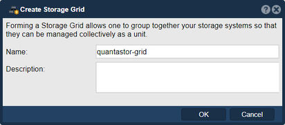
The node where the Grid is created initially will be elected as the initial primary/master node for the grid. The primary node has an additional role in that it acts as a conduit for intercommunication of grid state updates across all nodes in the grid. This additional role has minimal CPU and memory impact.
- Select the Storage Management tab and click the Create Grid button under the Storage System Grid section, or right-click on the System under Storage System and select Create Management Grid...
- Name: The Grid name can be set to anything.
After pressing OK, QuantaStor will reconfigure the node to create a single-node Grid.
Add Remaining Nodes to the Grid
Now that the Grid is created and the Primary node is a member, proceed to add all the additional systems. Note that this should be done from the Primary node's WebUI.
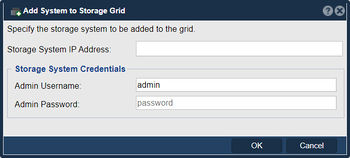
- Click on the Add System button in the Storage Management ribbon bar or right click on the Grid and select Add System to Grid...
- IP or hostname for the node to add
- Username for an Administrative user (default is admin)
- Password to authenticate
Repeat this process for each node to be added to the QuantaStor Grid. The Grid and member Systems can be managed by connecting to the WebUI of any of the members. It is not necessary to connect to the master node.
Preferred Grid IP
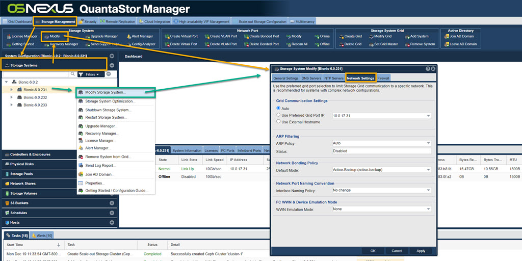
System to System communication typically works itself out automatically but it is recommended that you specify the network to be used for system inter-node communication for management operations. This is done by selecting the "Use Preferred Grid Port IP" from the in the "Network Settings" tab of the Storage System Modify dialog by right-clicking on each system in the grid and select 'Modify Storage System...'.
Note regarding User Access Security
Be aware that the management user accounts across the systems will be merged as part of joining the Grid. This includes the admin user account. In the event that there are duplicate user accounts, the user accounts in the currently elected primary/master node takes precedence.
Network Time Protocol (NTP) Configuration
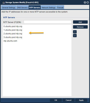
NTP is a system to make sure that the clock on computers is accurate. It is particularly important in Ceph cluster deployments that the clock be accurate. When the clocks on two or more systems are not synchronized it is called clock skew. Clock skew can happen for a few different reasons, most commonly:
- NTP server setting is not configured on one or more systems (use the Modify Storage System dialog to configure)
- NTP server is not accessible due to firewall configure issues
- No secondary NTP server is specified so the outage of the primary is leading to skew issues
- NTP servers are offline
- Network configuration problem is blocking access to the NTP servers
Ensure NTP servers are configured for each System by right clicking on the System under the Storage System drawer and select Modify Storage System... and examine that you have valid NTP servers configured.
- Note that QuantaStor retains the Ubuntu default NTP servers, but this may need to be adjusted based on accessibility restrictions of the Ceph cluster's network.
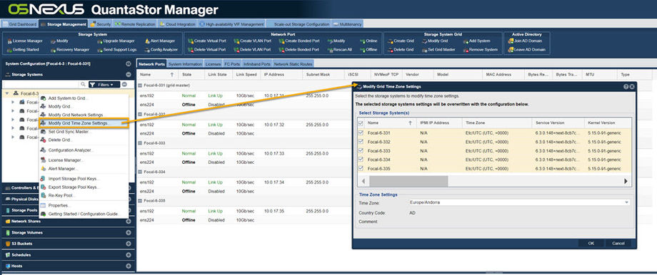
Alternatively, you can set all systems on a grid to the same time zone. Right click on the grid and select Modify Grid Time Zone Settings. This will bring up a menu with all of the systems pre-selected, and you can change the time zone. You can also set them to all have the same Domain Suffix. This is also where you can set the NTP Server for the entire grid.
Front-end / Back-end Network Configuration
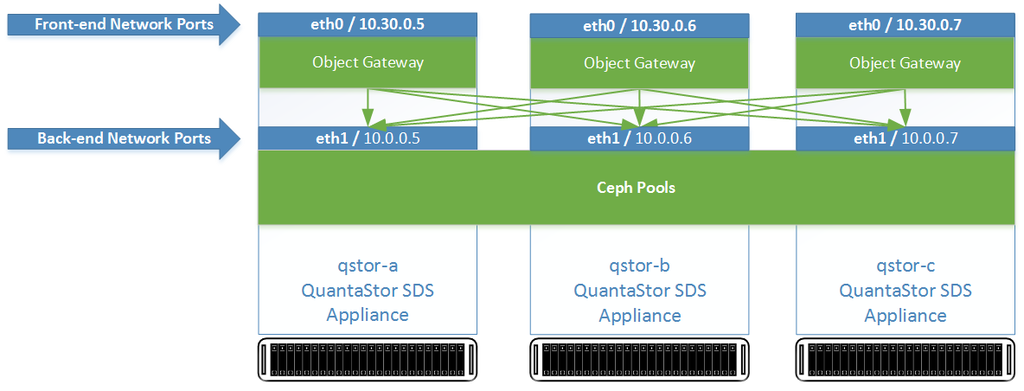
Networking for scale-out file and block storage deployments use a separate front-end and back-end network to cleanly separate the client communication to the front-end network ports (S3/SWIFT, iSCSI/RBD) from the inter-node communication on the back-end. This not only boosts performance, it increases the fault-tolerance, reliability and maintainability of the Ceph cluster. For all nodes one or more ports should be designated as the front-end ports and assigned appropriate IP addresses and subnets to enable client access. One can have multiple physical, virtual IPs, and VLANs used on the front-end network to enable a variety of clients to access the storage. The back-end network ports should all be physical ports but it is not required. A basic configuration looks like this:
Configuring Network Ports
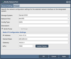
Update the configuration of each network port using the Modify Network Port dialog to put it on either the front-end network or the back-end network. The port names should be consistently configured across all system nodes such that all ethN ports are assigned IPs on the front-end or the back-end network but not a mix of both.
Enabling Object Storage Gateway Access
When the Object Portal checkbox is selected the port is now usable to access the QuantaStor web UI interface as it redirects port 80/443 traffic to the object storage daemon. Note, this will disable port 80/443 access to the QuantaStor Web Manager on the network ports where you Object Gateways are deployed. Note, you may use other network connections or HTTPS for web management access and the default alternate access port for the QuantaStor web management interface is port 8080.
