QuantaStor Setup Workflows: Difference between revisions
| Line 6: | Line 6: | ||
=== Minimum Hardware Requirements === | === Minimum Hardware Requirements === | ||
The High Availability for Storage Pool feature requires Front-End nodes that will serve access to the CLients for Block or File Storage and backend storafe via SAS or FC/iSCSI that can be used to provide a shared STorage device between the front end nodes. | |||
Front-End: | |||
* 2x (or more) QuantaStor appliances which will be configured as front-end ''controller nodes'' | * 2x (or more) QuantaStor appliances which will be configured as front-end ''controller nodes'' | ||
Back-End: | |||
* 2x (or more) QuantaStor appliance configured as back-end ''data nodes'' with SAS or SATA disk | * 2x (or more) QuantaStor appliance configured as back-end ''data nodes'' with SAS or SATA disk | ||
- or - | |||
* High-performance SAN (FC/iSCSI) connectivity between front-end ''controller nodes'' and back-end ''data nodes'' | * High-performance SAN (FC/iSCSI) connectivity between front-end ''controller nodes'' and back-end ''data nodes'' | ||
Revision as of 15:19, 14 January 2016
The following workflows are intended as a GO-TO guide which outlines the basic steps for initial appliance and grid configuration. More detailed information on each specific area can be found in the Administrators Guide.
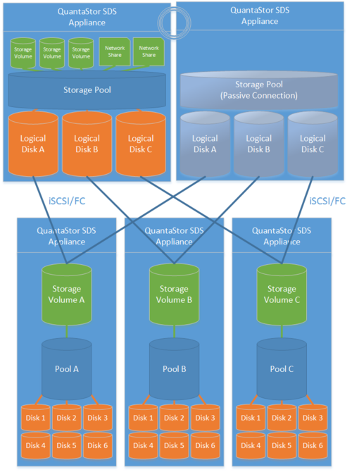
Highly-Available SAN/NAS Storage (Tiered SAN, ZFS based Storage Pools)
Minimum Hardware Requirements
The High Availability for Storage Pool feature requires Front-End nodes that will serve access to the CLients for Block or File Storage and backend storafe via SAS or FC/iSCSI that can be used to provide a shared STorage device between the front end nodes.
Front-End:
- 2x (or more) QuantaStor appliances which will be configured as front-end controller nodes
Back-End:
- 2x (or more) QuantaStor appliance configured as back-end data nodes with SAS or SATA disk
- or -
- High-performance SAN (FC/iSCSI) connectivity between front-end controller nodes and back-end data nodes
Setup Process
All Appliances
- Add your license keys, one unique key for each appliance
- Setup static IP addresses on each appliance (DHCP is the default and should only be used to get the appliance initially setup)
- Right-click on the storage system and set the DNS IP address (eg 8.8.8.8), and your NTP server IP address
Back-end Appliances (Data Nodes)
- Setup each back-end data node appliance as per basic appliance configuration with one or more storage pools each with one storage volume per pool.
- Ideal pool size is 10 to 20 drives, you may need to create multiple pools per back-end appliance.
- SAS is recommended but enterprise SATA drives can also be used
- HBA(s) or Hardware RAID controller(s) can be used for storage connectivity
Front-end Appliances (Controller Nodes)
- Connectivity between the front-end and back-end nodes can be FC or iSCSI
FC Based Configuration
- Create Host entries, one for each front-end appliance and add the WWPN of each of the FC ports on the front-end appliances which will be used for intercommunication between the front-end and back-end nodes.
- Direct point-to-point physical cabling connections can be made in smaller configurations to avoid the cost of an FC switch. Here's a guide that can help with some advice on FC zone setup for larger configurations using a back-end fabric.
- If you're using a FC switch you should use a fabric topology that'll give you fault tolerance.
- Back-end appliances must use Qlogic QLE 8Gb or 16Gb FC cards as QuantaStor can only present Storage Volumes as FC target LUNs via Qlogic cards.
iSCSI Based Configuration
- It's important but not required to separate the networks for the front-end (client communication) vs back-end (communicate between the control and data appliances).
- For iSCSI connectivity to the back-end nodes, create a Software iSCSI Adapter by going to the Hardware Controllers & Enclosures section and adding a iSCSI Adapter. This will take care of logging into and accessing the back-end storage. The back-end storage appliances must assign their Storage Volumes to all the Hosts for the front-end nodes with their associated iSCSI IQNs.
- Right-click to Modify Network Port of each port you want to disable client iSCSI access on. If you have 10GbE be sure to disable iSCSI access on the slower 1GbE ports used for management access and/or remote-replication.
HA Network Setup
- Make sure that eth0 is on the same network on both appliances
- Make sure that eth1 is on the same but separate network from eth0 on both appliances
- Create the Site Cluster with Ring 1 on the first network and Ring 2 on the second network, both front-end nodes should be in the Site Cluster, back-end nodes can be left out. This establishes a redundant (dual ring) heartbeat between the front-end appliances which will be used to detect hardware problems which in turn will trigger a failover of the pool to the passive node.
HA Storage Pool Setup
- Create a Storage Pool on the first front-end appliance (ZFS based) using the physical disks which have arrived from the back-end appliances.
- QuantaStor will automatically analyze the disks from the back-end appliances and stripe across the appliances to ensure proper fault-tolerance across the back-end nodes.
- Create a Storage Pool HA Group for the pool created in the previous step, if the storage is not accessible to both appliances it will block you from creating the group.
- Create a Storage Pool Virtual Interface for the Storage Pool HA Group. All NFS/iSCSI access to the pool must be through the Virtual Interface IP address to ensure highly-available access to the storage for the clients.
- Enable the Storage Pool HA Group. Automatic Storage Pool fail-over to the passive node will now occur if the active node is disabled or heartbeat between the nodes is lost.
- Test pool failover, right-click on the Storage Pool HA Group and choose 'Manual Failover' to fail-over the pool to another node.
Standard Storage Provisioning
- Create one or more Network Shares (CIFS/NFS) and Storage Volumes (iSCSI/FC)
- Create one or more Host entries with the iSCSI initiator IQN or FC WWPN of your client hosts/servers that will be accessing block storage.
- Assign Storage Volumes to client Host entries created in the previous step to enable iSCSI/FC access to Storage Volumes.
Diagram of Completed Configuration
Minimum Hardware Requirements
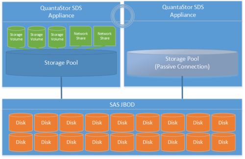
- 2x QuantaStor storage appliances acting as storage pool controllers
- 1x (or more) SAS JBOD connected to both storage appliances
- 2x to 100x SAS HDDs and/or SAS SSDs for pool storage, all data drives must be placed in the external shared JBOD
- 1x hardware RAID controller (for mirrored boot drives used for QuantaStor OS operating system)
- 2x 500GB HDDs (mirrored boot drives for QuantaStor SDS operating system)
- Boot drives should be 100GB to 1TB in size, both enterprise HDDs and DC grade SSD are suitable
Setup Process
Basics
- Login to the QuantaStor web management interface on each appliance
- Add your license keys, one unique key for each appliance
- Setup static IP addresses on each node (DHCP is the default and should only be used to get the appliance initially setup)
- Right-click to Modify Network Port of each port you want to disable iSCSI access on. If you have 10GbE be sure to disable iSCSI access on the slower 1GbE ports used for management access and/or remote-replication.
HA Network Config
- Right-click on the storage system and set the DNS IP address (eg 8.8.8.8), and your NTP server IP address
- Make sure that eth0 is on the same network on both appliances
- Make sure that eth1 is on the same but separate network from eth0 on both appliances
- Create the Site Cluster with Ring 1 on the first network and Ring 2 on the second network. This establishes a redundant (dual ring) heartbeat between the appliances.
HA Storage Pool Creation Setup
- Create a Storage Pool (ZFS based) on the first appliance using only disk drives that are in the external shared JBOD
- Create a Storage Pool HA Group for the pool created in the previous step, if the storage is not accessible to both appliances it will block you from creating the group.
- Create a Storage Pool Virtual Interface for the Storage Pool HA Group. All NFS/iSCSI access to the pool must be through the Virtual Interface IP address to ensure highly-available access to the storage for the clients. This ensures that connectivity is maintained in the event of fail-over to the other node.
- Enable the Storage Pool HA Group. Automatic Storage Pool fail-over to the passive node will now occur if the active node is disabled or heartbeat between the nodes is lost.
- Test pool fail-over, right-click on the Storage Pool HA Group and choose 'Manual Fail-over' to fail-over the pool to another node.
Storage Provisioning
- Create one or more Network Shares (CIFS/NFS) and Storage Volumes (iSCSI/FC)
- Create one or more Host entries with the iSCSI initiator IQN or FC WWPN of your client hosts/servers that will be accessing block storage.
- Assign Storage Volumes to client Host entries created in the previous step to enable iSCSI/FC access to Storage Volumes.
Diagram of Completed Configuration
Scale-out NFS/CIFS File Storage (Gluster based)
Minimum Hardware Requirements
- 3x QuantaStor storage appliances (up to 32x appliances)
- 5x to 100x HDDs or SSD for data storage per appliance
- 1x hardware RAID controller
- 2x 500GB HDDs (for mirrored hardware RAID device for QuantaStor OS boot/system disk)
Setup Process
- Login to the QuantaStor web management interface on each appliance
- Add your license keys, one unique key for each appliance
- Setup static IP addresses on each node (DHCP is the default and should only be used to get the appliance initially setup)
- Right-click on the storage system, choose 'Modify Storage System..' and set the DNS IP address (eg: 8.8.8.8), and the NTP server IP address (important!)
- Use the same Modify Storage System dialog set a unique host name for each for appliance.
- Setup separate front-end and back-end network ports (eg eth0 = 10.0.4.5/16, eth1 = 10.55.4.5/16) for NFS/CIFS traffic and Gluster traffic (a single network will work but is not optimal)
- Create a Grid out of the 3 or more appliances (use Create Grid then add the other two nodes using the Add Grid Node dialog)
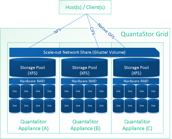
- Create hardware RAID5 units using 5 disks per RAID unit (4d + 1p) on each node until all HDDs have been used (see Hardware Enclosures & Controllers section, right-click on the controller to create new hardware RAID units)
- Create a XFS based Storage Pool using the Create Storage Pool dialog for each Physical Disk that comes from the hardware RAID controllers. There will be one XFS based storage pool for each hardware RAID5 unit.
- Select the Scale-out File Storage tab and choose 'Peer Setup' from the toolbar. In the dialog check the box for Autoconfigure Gluster Peer Connections. It will take a minute for all the connections to appear in the Gluster Peers section.
- Now that the peers are all connected we can provision scale-out NAS shares by using the Create Gluster Volume dialog.
- Gluster Volumes also appear as Network Shares in the Network Shares section and can be further configured to apply CIFS/NFS specific settings.
Diagram of Completed Configuration
Scale-out iSCSI Block Storage (Ceph based)
Minimum Hardware Requirements
- 3x QuantaStor storage appliances minimum (up to 64x appliances)
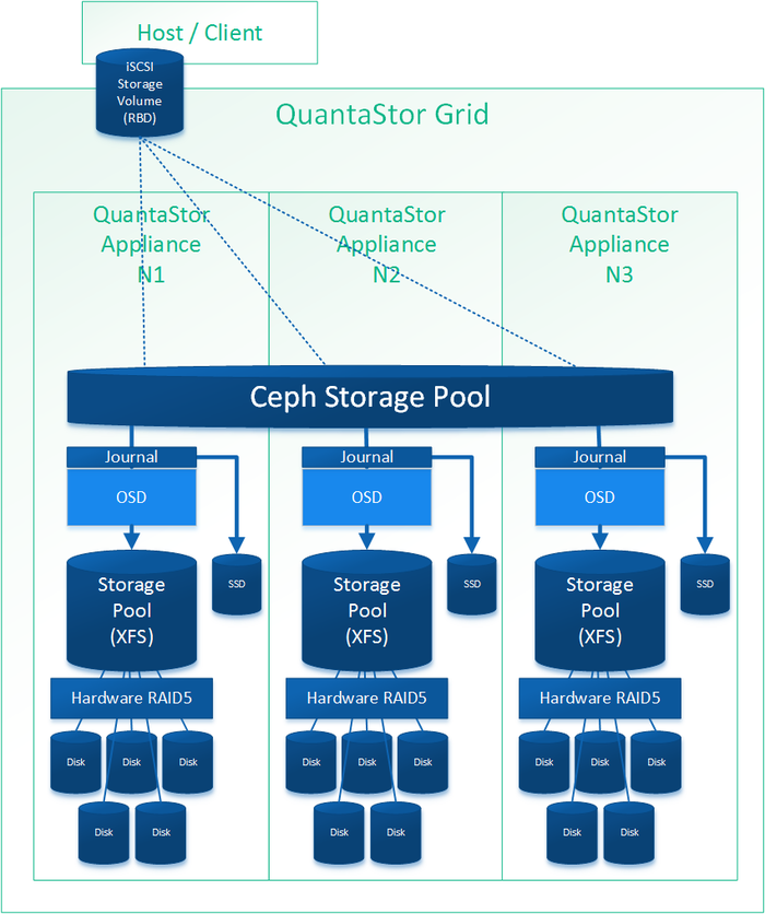
- 1x write endurance SSD device per appliance to make journal devices from. Have 1x SSD device for each 4x Ceph OSDs.
- 5x to 100x HDDs or SSD for data storage per appliance
- 1x hardware RAID controller for OSDs (SAS HBA can also be used but RAID is faster)
Setup Process
- Login to the QuantaStor web management interface on each appliance
- Add your license keys, one unique key for each appliance
- Setup static IP addresses on each node (DHCP is the default and should only be used to get the appliance initially setup)
- Right-click on the storage system, choose 'Modify Storage System..' and set the DNS IP address (eg: 8.8.8.8), and the NTP server IP address (important!)
- Setup separate front-end and back-end network ports (eg eth0 = 10.0.4.5/16, eth1 = 10.55.4.5/16) for iSCSI and Ceph traffic respectively
- Create a Grid out of the 3 appliances (use Create Grid then add the other two nodes using the Add Grid Node dialog)
- Create hardware RAID5 units using 5 disks per RAID unit (4d + 1p) on each node until all HDDs have been used (see Hardware Enclosures & Controllers section for Create Hardware RAID Unit)
- Create Ceph Cluster using all the appliances in your grid that will be part of the Ceph cluster, in this example of 3 appliances you'll select all three.
- Use OSD Multi-Create to setup all the storage, in that dialog you'll select some SSDs to be used as Journal Devices and the HDDs to be used for data storage across the cluster nodes. Once selected click OK and QuantaStor will do the rest.
- Create a scale-out storage pool by going to the Scale-out Block Storage section, then choose the Ceph Storage Pool section, then create a pool. It will automatically select all the available OSDs.
- Create a scale-out block storage device (RBD / RADOS Block Device) by choosing the 'Create Block Device/RBD' or by going to the Storage Management tab and choosing 'Create Storage Volume' and then select your Ceph Pool created in the previous step.
At this point everything is configured and a block device has been provisioned. To assign that block device to a host for access via iSCSI, you'll follow the same steps as you would for non-scale-out Storage Volumes.
- Go to the Hosts section then choose Add Host and enter the Initiator IQN or WWPN of the host that will be accessing the block storage.
- Right-click on the Host and choose Assign Volumes... to assign the scale-out storage volume(s) to the host.
Repeat the Storage Volume Create and Assign Volumes steps to provision additional storage and to assign it to one or more hosts.
Diagram of Completed Configuration
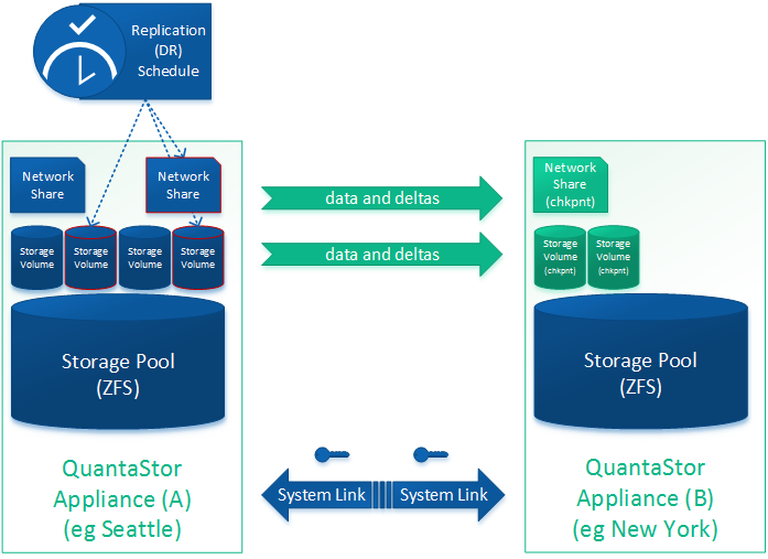
DR / Remote-replication of SAN/NAS Storage (ZFS based Storage Pools)
Minimum Hardware Requirements
- 2x QuantaStor storage appliances each with a ZFS based Storage Pool
- Storage pools do not need to be the same size or and the hardware and disk types on the appliances can be asymmetrical (non-matching)
- Replication can be cascaded across many appliances.
- Replication can be N-way replicating from one-to-many or many-to-one appliance.
- Replication is incremental so only the changes are sent
- Replication is supported for both Storage Volumes and Network Shares
- Replication interval can be set to as low as 15 minutes for a near-CDP configuration or scheduled to run at specific hours on specific days
- All data is AES 256 encrypted on the wire.
Setup Process
- Select the remote-replication tab and choose 'Create Storage System Link'. This will exchange keys between the two appliances so that a replication schedule can be created. You can create an unlimited number of links. The link also stores information about the ports to be used for remote-replication traffic
- Select the Volume & Share Replication Schedules section and choose Create in the toolbar to bring up the dialog to create a new remote replication schedule
- Select the replication link that will indicate the direction of replication.
- Select the storage pool on the destination system where the replicated shares and volumes will reside
- Select the times of day or interval at which replication will be run
- Select the volumes and shares to be replicated
- Click OK to create the schedule
- The Remote-Replication/DR Schedule is now created. If you chose an interval based replication schedule it will start momentarily. If you chose one that runs at specific times of day it will not trigger until that time.
- You can test the schedule by using Trigger Schedule it to start immediately.
