Difference between revisions of "HA Cluster Setup (JBODs)"
(Created page with "__TOC__ <!-- Removed Overview header, replaced with Introduction and reduced to H2 for TOC alignment/navigation --> == Introduction == QuantaStor's clustered storage pool con...") |
m (→Site Cluster Configuration) |
||
| Line 136: | Line 136: | ||
[[File:osn_clustered_jbod_config.png|640px]] | [[File:osn_clustered_jbod_config.png|640px]] | ||
| − | + | [[Template:ClusteredHACommon]] | |
| − | + | {{Template:ClusteredHACommon}} | |
| − | + | ||
| − | [[ | + | |
| − | + | ||
| − | + | ||
| − | + | ||
| − | + | ||
| − | + | ||
| − | : | + | |
| − | + | ||
| − | + | ||
| − | + | ||
| − | + | ||
| − | + | ||
| − | + | ||
| − | + | ||
| − | + | ||
| − | + | ||
| − | + | ||
| − | + | ||
| − | + | ||
| − | + | ||
| − | + | ||
| − | + | ||
| − | + | ||
| − | + | ||
| − | + | ||
| − | + | ||
| − | + | ||
| − | + | ||
| − | + | ||
| − | + | ||
| − | + | ||
| − | + | ||
| − | + | ||
| − | + | ||
| − | + | ||
| − | + | ||
| − | + | ||
| − | + | ||
| − | + | ||
| − | + | ||
| − | + | ||
| − | + | ||
| − | + | ||
| − | + | ||
| − | + | ||
| − | + | ||
| − | + | ||
| − | + | ||
| − | + | ||
| − | + | ||
| − | + | ||
| − | + | ||
| − | + | ||
== Cluster HA Storage Pool Creation == | == Cluster HA Storage Pool Creation == | ||
Revision as of 15:22, 4 March 2016
Contents
- 1 Introduction
- 2 High Availability Tiered SAN/ZFS based SAN/NAS Storage Layout
- 3 High Availability Shared JBOD/ZFS based SAN/NAS Storage Layout
- 4 Site Cluster Configuration
- 5 Cluster HA Storage Pool Creation
- 6 Storage Pool High-Availability Group Configuration
- 7 High Availability Group Fail-over
- 8 Troubleshooting for HA Storage Pools
Introduction
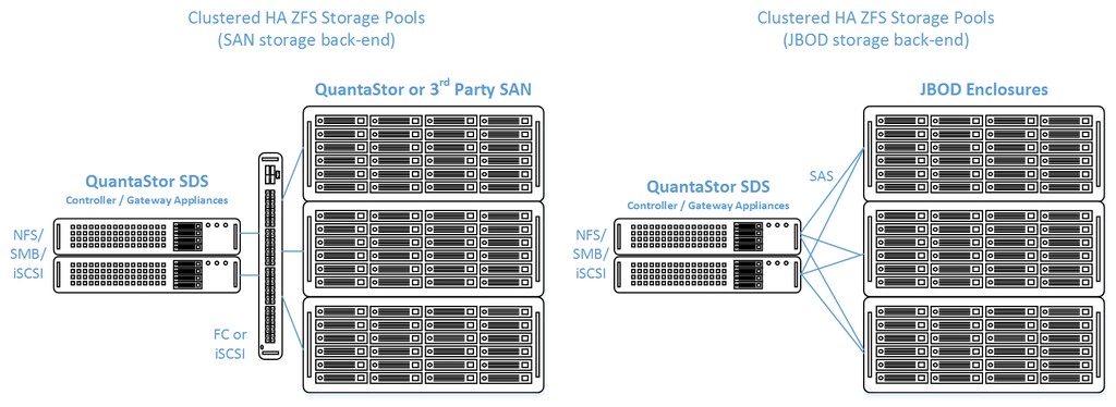
QuantaStor's clustered storage pool configurations ensure high-availability (HA) in the event of a node outage or storage connectivity to the active node is lost. From a hardware perspective a QuantaStor deployment of one or more clustered storage pools requires at least two QuantaStor appliances so that automatic fail-over can occur in the event that the active appliance goes offline. Another requirement of these configurations is that the disk storage devices for the highly-available pool cannot be in either of the server units. Rather the storage must come from an external source which can be as simple as using one or more SAS JBOD enclosures or for higher performance configurations could be a SAN delivering block storage (LUNs) to the QuantaStor front-end appliances over FC (preferred) or iSCSI. The following two sections outline the minimum hardware requirements for each.
Setup and Configuration Overview
- Install both QuantaStor Appliances with the most recent release of QuantaStor.
- Apply the QuantaStor Gold, Platinum or Cloud Edition license key to each appliance. Each key must be unique.
- Create a Grid and join both QuantaStor Appliances to the grid.
- Configure SAS Hardware and Verify connectivity of SAS cables from HBAs to JBOD
- LSI SAS HBA's must be configured with the 'Boot Support' MPT BIOS option configured to 'OS only' mode.
- Verify that the SAS disks installed in both systems appear to both head nodes in the WebUI Hardware Enclosures and Controllers section.
- Create Network and Cluster heartbeat configuration and Verify network connectivity
- At least two NICs are required for a HA Cluster configuration with separate networks
- Create a Storage Pool
- Use only drives from shared storage
- Create Storage Pool HA Group
- Create one or more Storage Pool HA Virtual Interfaces
- Activate the Storage Pool
- Test failover
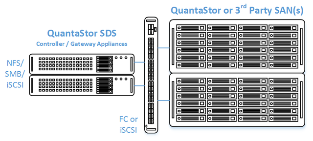
High Availability Tiered SAN/ZFS based SAN/NAS Storage Layout
In this configuration the QuantaStor front-end controller appliances are acting as a gateway to the storage in the SANs on the back-end. QuantaStor has been tested with NetApp and HP MSA 3rd party SANs as back-end storage as well as with QuantaStor SDS as a back-end SAN. Please contact support@osnexus.com for the latest HCL for 3rd party SAN support or to get additional SAN support added to the HCL.
Minimum Hardware Requirements
- 2x (or more) QuantaStor appliances which will be configured as front-end controller nodes
- 2x (or more) QuantaStor appliance configured as back-end data nodes with SAS or SATA disk
- High-performance SAN (FC/iSCSI) connectivity between front-end controller nodes and back-end data nodes
Setup Process
All Appliances
- Login to the QuantaStor web management interface on each appliance
- Add your license keys, one unique key for each appliance
- Setup static IP addresses on each appliance (DHCP is the default and should only be used to get the appliance initially setup)
- Right-click on the storage system and set the DNS IP address (eg 8.8.8.8), and your NTP server IP address
Back-end Appliances (Data Nodes)
- Setup each back-end data node appliance as per basic appliance configuration with one or more storage pools, each with one storage volume per pool.
- Ideal pool size is 10 to 20 drives, you may need to create multiple pools per back-end appliance.
- SAS is recommended but enterprise SATA drives can also be used
- HBA(s) or Hardware RAID controller(s) can be used for storage connectivity
Front-end Appliances (Controller Nodes)
- Connectivity between the front-end and back-end nodes can be FC or iSCSI
FC SAN Back-end Configuration
- Create Host entries, one for each front-end appliance and add the WWPN of each of the FC ports on the front-end appliances which will be used for intercommunication between the front-end and back-end nodes.
- Direct point-to-point physical cabling connections can be made in smaller configurations to avoid the cost of an FC switch. Here's a guide that can help with some advice on FC zone setup for larger configurations using a back-end fabric.
- If you're using a FC switch you should use a fabric topology that will give you fault tolerance.
- Back-end appliances must use Qlogic QLE 8Gb or 16Gb FC cards as QuantaStor can only present Storage Volumes as FC target LUNs via Qlogic cards.
iSCSI SAN Back-end Configuration
- It is highly recommended to separate the networks for the front-end (client communication) vs back-end (communicate between the control and data appliances).
- For iSCSI connectivity to the back-end nodes, create a Software iSCSI Adapter by going to the Hardware Controllers & Enclosures section and adding a iSCSI Adapter. This will take care of logging into and accessing the back-end storage. The back-end storage appliances must assign their Storage Volumes to all the Hosts for the front-end nodes with their associated iSCSI IQNs.
- Right-click to Modify Network Port of each port you want to disable client iSCSI access on. If you have 10GbE be sure to disable iSCSI access on the slower 1GbE ports used for management access and/or remote-replication.
HA Network Setup
- Make sure that eth0 is on the same network on both appliances
- Make sure that eth1 is on the same but separate network from eth0 on both appliances
- Create the Site Cluster with Ring 1 on the first network and Ring 2 on the second network, both front-end nodes should be in the Site Cluster, back-end nodes can be left out. This establishes a redundant (dual ring) heartbeat between the front-end appliances which will be used to detect hardware problems which in turn will trigger a failover of the pool to the passive node.
HA Storage Pool Setup
- Create a Storage Pool on the first front-end appliance (ZFS based) using the physical disks which have arrived from the back-end appliances.
- QuantaStor will automatically analyze the disks from the back-end appliances and stripe across the appliances to ensure proper fault-tolerance across the back-end nodes.
- Create a Storage Pool HA Group for the pool created in the previous step. If the storage is not accessible to both appliances, it will block you from creating the group.
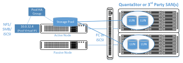
- Create a Storage Pool Virtual Interface for the Storage Pool HA Group. All NFS/iSCSI access to the pool must be through the Virtual Interface IP address to ensure highly-available access to the storage for the clients.
- Enable the Storage Pool HA Group. Automatic Storage Pool fail-over to the passive node will now occur if the active node is disabled or heartbeat between the nodes is lost.
- Test pool failover, right-click on the Storage Pool HA Group and choose 'Manual Failover' to fail-over the pool to another node.
Standard Storage Provisioning
- Create one or more Network Shares (CIFS/NFS) and Storage Volumes (iSCSI/FC)
- Create one or more Host entries with the iSCSI initiator IQN or FC WWPN of your client hosts/servers that will be accessing block storage.
- Assign Storage Volumes to client Host entries created in the previous step to enable iSCSI/FC access to Storage Volumes.
Diagram of Completed Configuration
Minimum Hardware Requirements
- 2x QuantaStor storage appliances acting as storage pool controllers
- 1x (or more) SAS JBOD connected to both storage appliances
- 2x to 100x SAS HDDs and/or SAS SSDs for pool storage, all data drives must be placed in the external shared JBOD. Drives must be SAS that support Multi-port and SCSI3 Reservations, SATA drives are not supported.
- 1x hardware RAID controller (for mirrored boot drives used for QuantaStor OS operating system)
- 2x 500GB HDDs (mirrored boot drives for QuantaStor SDS operating system)
- Boot drives should be 100GB to 1TB in size, both enterprise HDDs and DC grade SSD are suitable
Storage Bridge Bay Support
Using a cluster-in-a-box or SBB (Storage Bridge Bay) system one can setup QuantaStor in a highly-available cluster configuration in a single 2U rack-mount unit. SBB units contain two hot-swap servers and a JBOD all-in-one and QuantaStor supports all SuperMicro based SBB units. For more information on hardware options and SBB please contact your OSNEXUS reseller or our solution engineering team at sdr@osnexus.com.
Setup Process
All Appliances
- Login to the QuantaStor web management interface on each appliance
- Add your license keys, one unique key for each appliance
- Setup static IP addresses on each node (DHCP is the default and should only be used to get the appliance initially setup)
- Right-click to Modify Network Port of each port you want to disable iSCSI access on. If you have 10GbE be sure to disable iSCSI access on the slower 1GbE ports used for management access and/or remote-replication.
Heartbeat/Cluster Network Configuration
- Right-click on the storage system and set the DNS IP address (eg 8.8.8.8), and your NTP server IP address
- Make sure that eth0 is on the same network on both appliances
- Make sure that eth1 is on the same but separate network from eth0 on both appliances
- Create the Site Cluster with Ring 1 on the first network and Ring 2 on the second network. This establishes a redundant (dual ring) heartbeat between the appliances.
HA Storage Pool Creation Setup
- Create a Storage Pool (ZFS based) on the first appliance using only disk drives that are in the external shared JBOD
- Create a Storage Pool HA Group for the pool created in the previous step, if the storage is not accessible to both appliances it will block you from creating the group.
- Create a Storage Pool Virtual Interface for the Storage Pool HA Group. All NFS/iSCSI access to the pool must be through the Virtual Interface IP address to ensure highly-available access to the storage for the clients. This ensures that connectivity is maintained in the event of fail-over to the other node.
- Enable the Storage Pool HA Group. Automatic Storage Pool fail-over to the passive node will now occur if the active node is disabled or heartbeat between the nodes is lost.
- Test pool fail-over, right-click on the Storage Pool HA Group and choose 'Manual Fail-over' to fail-over the pool to another node.
Storage Provisioning
- Create one or more Network Shares (CIFS/NFS) and Storage Volumes (iSCSI/FC)
- Create one or more Host entries with the iSCSI initiator IQN or FC WWPN of your client hosts/servers that will be accessing block storage.
- Assign Storage Volumes to client Host entries created in the previous step to enable iSCSI/FC access to Storage Volumes.
Diagram of Completed Configuration
Site Cluster Configuration
The Site Cluster represents a group of two or more systems that have an active heartbeat mechanism which is used to activate resource fail-over in the event that a resource (storage pool) goes offline. Site Clusters should be comprised of QuantaStor systems which are all in the same location but could span buildings within the same site. The heartbeat expects a low latency connection and is typically done via dual direct Ethernet cable connections between a pair of QuantaStor systems but could also be done with Ethernet switches in-between.
After the heart-beat rings are setup (Site Cluster) the HA group can be created for each pool and virtual IPs created within the HA group. All SMB/NFS/iSCSI access must flow through the virtual IP associated with the Storage Pool in order to ensure client up-time in the event of an automatic or manual fail-over of the pool to another system.
Grid Setup
Both systems must be in the same grid before the Site Cluster can be created. Grid creation takes less than a minute and the buttons to create the grid and additional systems to the grid are in the ribbon bar. QuantaStor systems can only be members of a single grid at a time but up to 64 systems can be added to a grid which can contain multiple independent Site Clusters.
Site Cluster Network Configuration
Before beginning, note that when you create the Site Cluster it will automatically create the first heartbeat ring (Cluster Ring) on the network that you have specified. This can be a direct connect private network between two systems or the ports could be connected to a switch. The key requirement is that the name of the ports used for the Cluster Ring must be the same. For example, if eth0 is the port on System A with IP 10.3.0.5/16 then you must configure the matching eth0 network port on System B with an IP on the same network (10.3.0.0/16), for example 10.3.0.7/16.
- Each Highly Available Virtual Network Interface requires Three IP Addresses be configured in the same subnet: one for the Virtual Network Interface and one for each Network Device on each QuantaStor Storage System.
- Both QuantaStor systems must have unique IP address for their Network devices.
- Each Management and Data network must be on separate subnets to allow for proper routing of requests from clients and proper failover in the event of a network failure.
To change the configuration of the network ports to meet the above requirements please see the section on [Network Ports].
Heartbeat Networks must be Dedicated
The network subnet used for heartbeat activity should not be used for any other purpose besides the heartbeat. Using the above example, the network of 10.3.x.x/16 and 10.4.x.x/16 are being used for the heartbeat traffic. Traffic for client communication such as NFS/iSCSI traffic to the system via the storage pool virtual IP (see next section) must be on a separate network, for example, 10.111.x.x/16. Mixing the HA heartbeat traffic with the client communication traffic can cause a false-positive failover event to occur.
Creating the Site Cluster
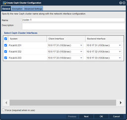
The Site Cluster name is a required field and can be set to anything you like, for example ha-pool-cluster. The location and description fields are optional. Note that all of the network ports selected are on the same subnet with unique IPs for each node. These are the IP addresses that will be used for heartbeat communication. Client communication will be handled later in the Creating a Virtual IP in the Storage Pool HA Group section.
Navigation: High-availability VIF Management --> Site Clusters --> Site Cluster --> Create Site Cluster (toolbar)
Dual Heartbeat Rings Advised
Any cluster intended for production deployment should have at least two heartbeat Cluster Rings configured. Configurations using a single heartbeat Cluster Ring are fragile and are only suitable for test configurations not intended for production use. Without dual rings in place, it is very easy for a false positive failover event to occur, making any network changes likely to activate a fail-over inadvertently.
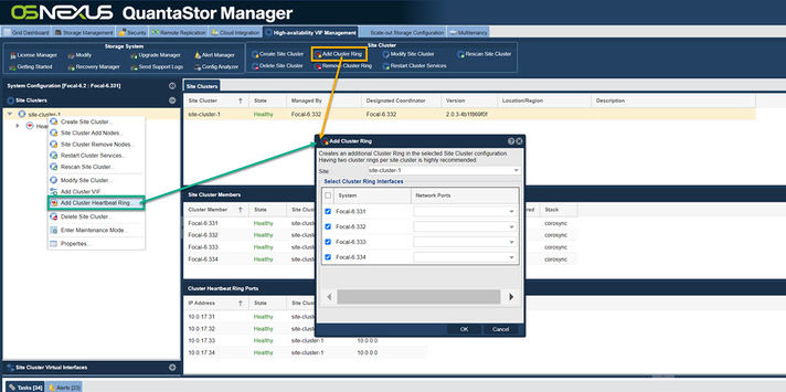
After creating the Site Cluster, an initial Cluster Ring will exist. Create a second by clicking the 'Add Cluster Ring' button from the toolbar.
Navigation: High-availability VIF Management --> Site Clusters --> Site Cluster --> Add Cluster Ring (toolbar)
Cluster HA Storage Pool Creation
Creation of a HA storage pool is the same as the process for creating a non-HA storage pool. The pool should be created on the appliance that will be acting as the primary node for the pool but that is not required. Support for Encrypted Storage Pools is available in QuantaStor v3.17 and above.
Disk Connectivity Pre-checks
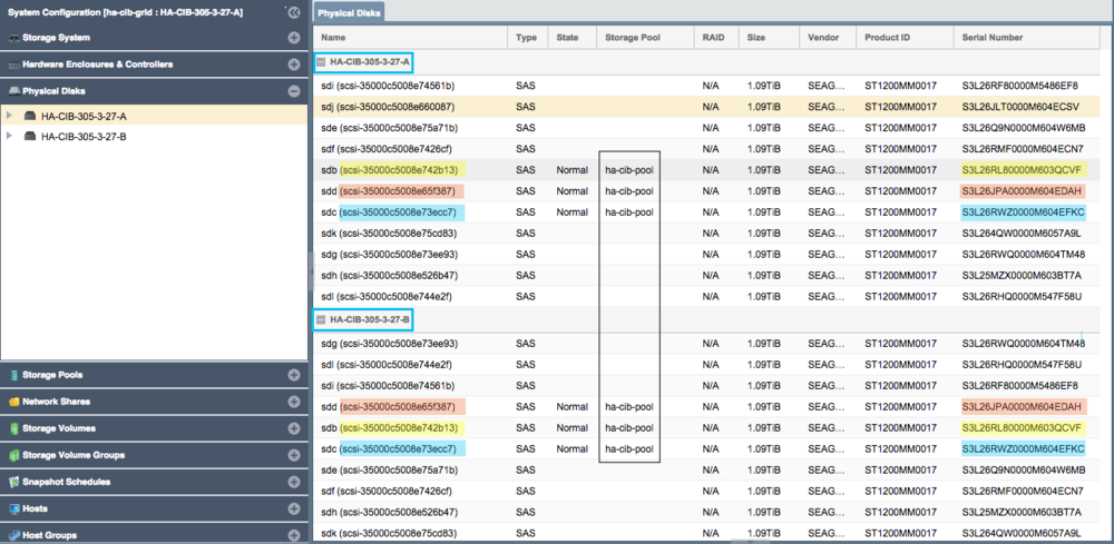
Any storage Storage Pool which is to be made Highly-Available must be configured such that both appliances used in the HA configuration both have access to all disks used by the storage pool. This necessarily requires that all devices used by a storage pool (including cache, log, and hot-spare devices) must be in a shared external JBOD or SAN. Verify connectivity to the back-end storage used by the Storage Pool via the Physical Disks section of the WebUI.
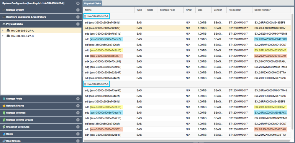
- Note how devices with the same ID/Serial Numbers are visible on both storage appliances. This is a strict requirement for creating Storage Pool HA Groups.
- Dual-ported SAS drives must be used when deploying a HA configuration with a JBOD backend.
- Enterprise and Data Center (DC) grade SATA drives can be used in a Tiered SAN HA configuration with QuantaStor appliances used as back-end storage rather than a JBOD.
Storage Pool Creation (ZFS)
Once the disks have been verified as visible to both nodes in the cluster, proceed with Storage Pool creation using the following steps:
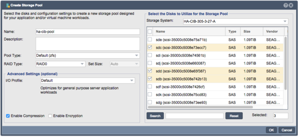
- Configure the Storage Pool on one of the nodes using the Create Storage Pool dialog.
- Provide a Name for the Storage Pool
- Choose the Pool Type of Default (zfs)
- Choose the RAID Type and I/O profile that will suit your use case best, more details are available in the Soultion Design Guide.
- Select the shared storage disks that you would like to use that will suit your RAID type and that were previosuly confirmed to be accessible to both QuantaStor Appliances.
- Click 'OK' to create the Storage Pool once all of the Storage pool settings are configured correctly.
Back-end Disk/LUN Connectivity Checklist
Following pool creation, return to the Physical Disks view and verify that the storage pool disks show the Storage Pool name for all disks on both nodes.
See the Troubleshooting section below for suggestions if you are having difficulties establishing shared disk presentation between nodes.
Storage Pool High-Availability Group Configuration
Now that the Site Cluster has been created (including the two appliances that will be used in the cluster) and the Storage Pool has been created to be made HA, the final steps are to create a Storage Pool HA Group for the pool and then to make a Storage Pool HA Virtual IP (VIF) in the HA group. If you have not setup a Site Cluster with two cluster/heartbeat rings for redundancy please go to the previous section and set that up first.
Creating the Storage Pool HA Group
The Storage Pool HA Group is an administrative object in the grid which associates one or more virtual IPs with a HA Storage Pool and is used to take actions such as enabling/disabling automatic fail-over, and execution of manually activated fail-over operations. Storage Pool HA Group creation be performed via a number of short cuts:
- Under the Storage Management tool window, expand the Storage Pool drawer, right click and select Create High Availability Group
- Under the Storage Management tool window, expand the Storage Pool drawer and click the Create Group button under Storage Pool HA Group in the ribbon bar
- Under the High Availability tool window, click the Create Group button under Storage Pool HA Group in the ribbon bar
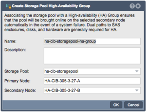
The Create Storage Pool High-Availability Group dialog will be pre-populated with values based on your available storage pool.
- The name can be customized if desired, but it is best practice to make it easy to determine which Storage Pool is being managed. Description is optional.
- Verify the intended pool is listed.
- Primary node will be set to the node with the storage pool currently imported.
- Select the Secondary node (if more than 2 nodes in the Site Cluster)
After creating the Storage Pool High-Availability Group you will need to create a Virtual Network Interface.
High-Availability Virtual Network Interface Configuration
The High-Availability Virtual Network Interface provides the HA Group with a Virtual IP that can fail-over with the group between nodes, providing client connections with a consistent connection to the Storage Pool/Shares regardless of what node currently has the Storage Group imported. This will require another IP address separate from any in use for the Storage Appliances.
Adding a HA Virtual Network Interface can be performed by opening the High Availability window via the toolbar and clicking the Add Interface button in the ribbon bar
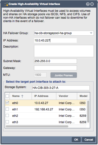
When creating a HA Virtual Interface, verify that the intended HA Failover Group is selected. The IP Address provided here will be the one clients should use to access the Storage Pool and associated Shares or Volumes. Ensure that an appropriate Subnet is set and the appropriate ethernet port for the address is selected at the bottom. If necessary a Gateway can be set as well, but if the Gateway will be the same as one already configured, it should be left blank.
- Note that this cannot be an IP address in use already in use in the network.
After creating the Virtual Network Interface, the new interface will be seen as a "Virtual Interface" in the System View/Network Port's tab in the WebUI.
HA Group Activation
Once the previous steps have all been completed, the High Availability Group is ready to be activated. Once the HA Group is activated, the Site Cluster will begin monitoring node membership and initiate fail-over of the Storage Pool (+Shares/Volumes) and the Virtual IP Address if the activate node is detected as offline or not responding via any of the available Heartbeat Rings. This is why redundant Heartbeat Rings are essential; with only one Heartbeat Ring any transient network interruption could result in unnecessary fail-over and service interruptions.
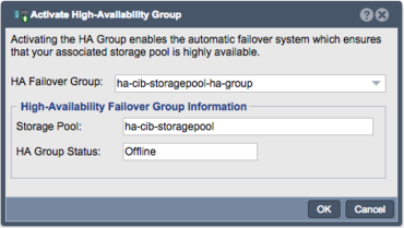
The High Availability Group can be activated by right Clicking on the High Availability Group and choosing Activate High Availability Group...
- The HA Group Status will show Offline because the group has not been activated yet
- Following activation the Storage Pool HA Group's icon in the drawer will remove the down arrow after activation is complete
High Availability Group Fail-over
Automatic HA Failover
Once the above steps have been completed, including Activation of the High Availability Group, the cluster will monitor node health and if a failure is detected on the node with ownership of the Shared Storage Pool, an Automatic HA Failover event will be triggered. An automatic fail-over of the Storage Group will perform a failover of the storage group to the secondary node, and all clients will regain access to the Storage Volumes and/or Network Share once the resources come online.
Manual Fail-over Testing
The final step in performing an initial High Availability configuration is to test that the Storage Pool HA Group can successfully fail-over between the Primary and Secondary nodes. The Manual Fail-over process provides a way to gracefully migrate the Storage Pool HA Group between nodes, and can be used to administratively move the Storage Pool to another node if required for some reason (such as for planned maintenance or other tasks that may interrupt usability of the primary node).
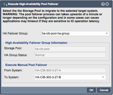
To trigger a Manual Failover for maintenance or for testing, right click on the High Availability Group and choose the Failover High Availability Group option. In the dialog, choose the node you would like to failover to and click 'ok' to start the manual failover or use the Manual Fail-over button on the High Availability ribbon bar.
- Fail-over will begin by stopping Network Share services and Storage Volume presentation
- The Virtual Network Interface will then be shutdown on that node
- The active node's SCSI3 PGR reservations will be cleared and the ZFS pool deported
- The fail-over target node will then import the ZFS pool and set SCSI3 PGR reservations
- The Virtual Network Interface will be started on the fail-over target node
- Network Shares and Storage Volumes will then be enabled on the fail-over target node
Use of the Virtual Network Interface means this process is transparent to clients and only creates a temporary interruption of service while the Storage Pool is brought online on the fail-over target.
Troubleshooting for HA Storage Pools
Expanding shortly with tips and suggestions on troubleshooting issues with Storage Pool HA Group setup issues...
Disks are not visible on all systems
If you don't see the storage pool name label on the pool's disk devices on both appliances use this checklist to verify possible connection or configuration problems.
- Make sure there is connectivity from both QuantaStor appliances used in the Site Cluster to the back-end shared JBOD for the storage pool or the back-end SAN.
- Verify FC/SAS cables are securely seated and link activity lights are active (FC).
- All drives used to create the storage pool must be SAS, FC, or iSCSI devices that support multi-port and SCSI3 Persistent Reservations.
- SAS JBOD should have at least two SAS Expansion ports. Having a JBOD with 3 or more expansions ports and Redundant SAS Expander/Environment Service Modules(ESM) is prefferred.
- SAS JBOD cables should be within standard SAS cable lengths (less than 15 meters) of the SAS HBA's installed in the QuantaStor appliances.
- Faster devices such as SSDs and 15K RPM platter disk should be placed in a separate enclosure from the NL-SAS disks to ensure best performance.
- Cluster-in-a-Box solutions provide these hardware requirements in a single HA QuantaStor Appliance and are recommended for small configurations (less than 25x drives)
The qs-util devicemap can be helpful when troubleshooting this issue.
Useful Tools
qs-iofence devstatus
The qs-iofence utility is helpful for the diagnosis and troubleshooting of SCSI reservations on disks used by HA Storage Pools.
# qs-iofence devstatus
- Displays a report showing all SCSI3 PGR reservations for devices on the system. This can be helpful when zfs pools will not import and "scsi reservation conflict" error messages are observed in the syslog.log system log.
qs-util devicemap
The qs-util devicemap utility is helpful for checking via the CLI what disks are present on the system. This can be extremely helpful when troubleshooting disk presentation issues as the output shows the Disk ID, and Serial Numbers, which can then be compared between nodes.
HA-CIB-305-3-27-A:~# qs-util devicemap | sort
...
/dev/sdb	/dev/disk/by-id/scsi-35000c5008e742b13, SEAGATE, ST1200MM0017, S3L26RL80000M603QCVF,
/dev/sdc	/dev/disk/by-id/scsi-35000c5008e73ecc7, SEAGATE, ST1200MM0017, S3L26RWZ0000M604EFKC,
/dev/sdd	/dev/disk/by-id/scsi-35000c5008e65f387, SEAGATE, ST1200MM0017, S3L26JPA0000M604EDAH,
/dev/sde	/dev/disk/by-id/scsi-35000c5008e75a71b, SEAGATE, ST1200MM0017, S3L26Q9N0000M604W6MB,
...
HA-CIB-305-3-27-B:~# qs-util devicemap | sort
...
/dev/sdb	/dev/disk/by-id/scsi-35000c5008e742b13, SEAGATE, ST1200MM0017, S3L26RL80000M603QCVF,
/dev/sdc	/dev/disk/by-id/scsi-35000c5008e73ecc7, SEAGATE, ST1200MM0017, S3L26RWZ0000M604EFKC,
/dev/sdd	/dev/disk/by-id/scsi-35000c5008e65f387, SEAGATE, ST1200MM0017, S3L26JPA0000M604EDAH,
/dev/sde	/dev/disk/by-id/scsi-35000c5008e75a71b, SEAGATE, ST1200MM0017, S3L26Q9N0000M604W6MB,
...
- Note that while many SAS JBODs will typically produce consistent assignment of /dev/sdXX lettering, FC/iSCSI attached storage will typically vary due to variation in how Storage Arrays respond to bus probes. The important parts to match between nodes are the /dev/disk/by-id/.... values, and the Serial Numbers in the final column.
